Smart Gateway Modular Design
The Smart Gateway hardware is a modular design which consists of the following internal modules.
- The Core Processor manages all functions of the Smart Gateway.
- The POE Power converter converts the 45-volt Power over Ethernet levels to the 5 volts needed for the Gateway.
- The RF Transceiver is used to receive messages from the RF Sensors and send them to the Core Processor.
- The Real-Time clock module provides time on power-up of the Smart Gateway if it cannot reach an online Time Server.
- The Dry Contact Relay module provides an open or closed contact on the Gateway Internal Failures.
- The LED status panel is the front panel of the SGW, featuring lights:
- Show the SGW is up and working.
- The Server light shows it is connected to the HTTPS server and sending data.
- The MQTT light indicates it is connected and sending data to the MQTT Broker.
The lights are Off if feature is disabled, Green if feature is on and working and Red if feature is on and Not working.
The basic modules that make the Smart Gateway are the housing including the from LED status lights, the Core Processor and the RF Transceiver.
The POE Module, the Real-Time Clock and Dry Contacts provide options to support installation site requirements.
Hardware Maintenance and Module Upgrades
Smart Gateway Internal
Turn upside down and remove the four screws.

Once the screws are removed trun the SGW over and remove the top. There is nothing attached to the top, but be careful not to pull the LED or Network panels off with the lid.
You should now see the insides of the SGW.
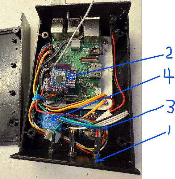
The arrows point to:
- Front Panel Lights
- Transceiver
- Real Time Clock Module
- Dry contact Relay Module
- Core Processor
- POE Converter (Not shown)
You will need to carefully cut and remove any wire ties.
Replacing the Core Processor
Currently, this replacement requires the Smart Gateway to be returned to the manufacturer for processing. Possible indications that the Core Processor is failing:
- The system does not work, and the front panel lights do not come on.
- The Control Panels do not come up.
- If the Control Panels are displayed, but no changes can be made, that indicates a Core Processor issue.
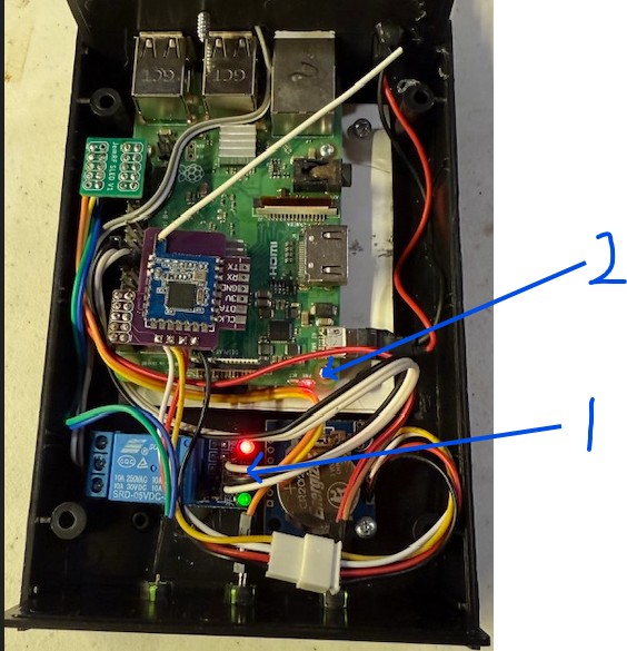
- Looking inside image C1, arrow 2 points to the red and green lights on the Core Processor are both on or both off.
- Upon power up, the proper activity of the Core Processor is indicated by the red and green lights. The red light will come on, followed by the green light flashing on and off.
 C1
C1
Install/Replace POE Power Converter
Currently, this replacement requires the Smart Gateway to be returned to the manufacturer for processing. Possible indications that the POE has failed:
- The system does not work, and the front panel lights do not come on.
- The Control Panels do not come up.
- Looking inside, there are no lights on.
Replacing RF Transceiver
The RF Transceive plugs into the Core Processor edge connector and provides the interface to the Internal battery-backed-up clock if installed. You will need a phillips screw driver to open the case.
Exchanging the Transceiver
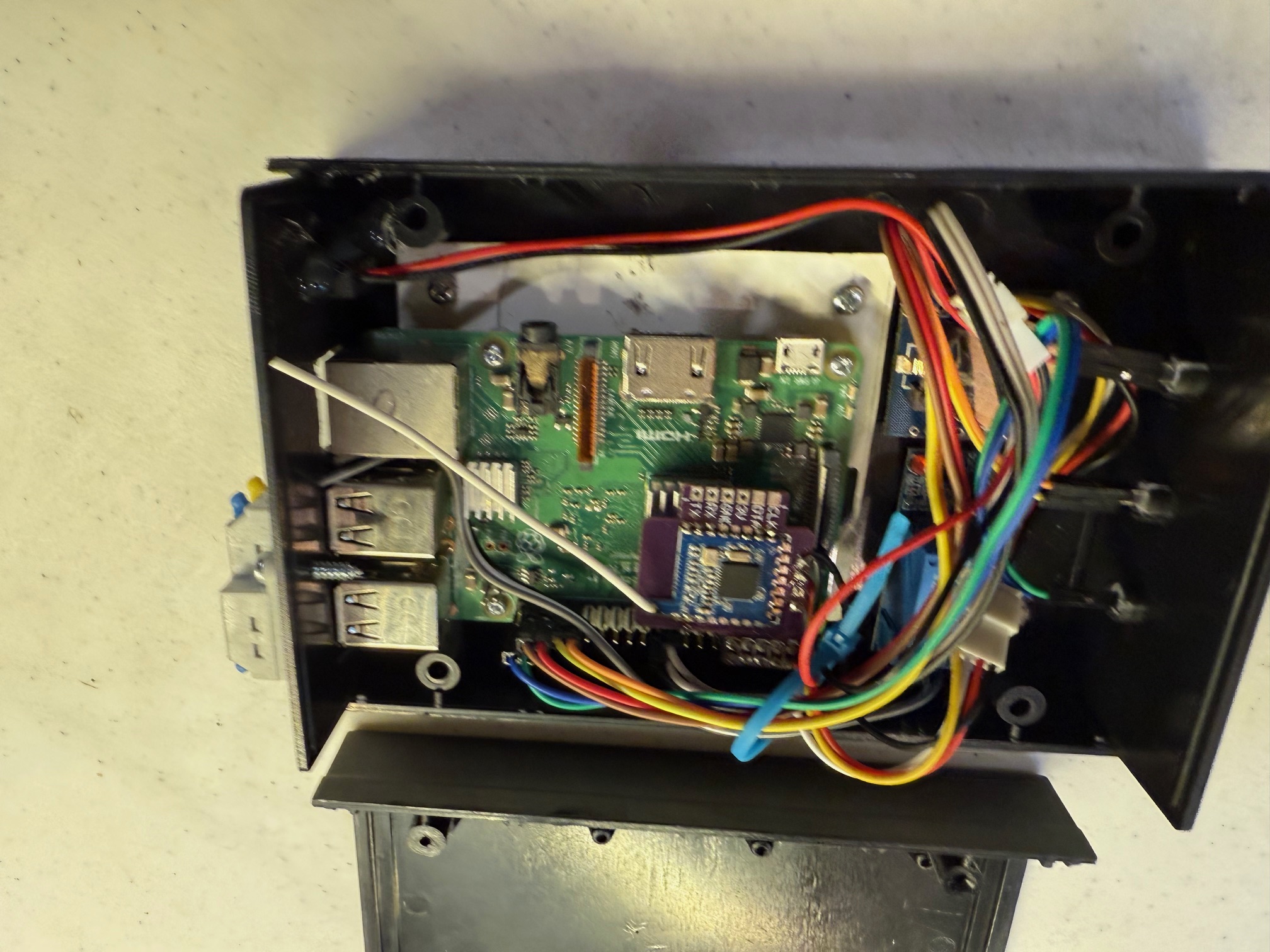
The Transceiver is plugged into the left end of the interface bus. For reference, the other end of the interface bus has the connections for the LED Status Panel. The image T1 below shows the transceiver module, and it is plugged into the interface bus.
![]() T1
T1
Note that the arrow shows that the module is correctly connected at the end of the interface bus.
This image T2 shows the Transceiver Module with the cables for connecting to the Real-Time Clock module if installed.
![]() T2
T2
To remove the Transceiver, just pull it up and off the interface bus. Then slide the connector apart that connects it to the RTC module.
 T3
T3
The arrow is used to denote the plug key for reconnecting it.
With the original Transceiver removed, plug the replacement transceiver onto the interface bus and then reconnect the RTC if used.
The following three images (T4, T5, and T6) show some common mistakes.
T4 arrow points to the pins showing on the Interface Bus. You should NOT see pins as pointed to.
![]() T4
T4
In T5 and T6, the arrow points to show the connector is to far forward.
![]() T5
T5
![]() T6
T6
Once all is reinstalled correctly, adjust the antenna (the white wire) to go as straight as possible up and to the far corner above the power connector, as shown below in T7. It is recommended to be a little too high and let the case lid push it down.
 T7
T7
Power Up verification
Once you have verified it is plugged in correctly and the antenna is aligned correctly, you can put the top cover back on and power it up.
To verify that it is working, check the Sensor List tab to see that your sensors appear in the list. If they do not appear after a few minutes, the System Gateway Ready Light will turn red, indicating that it does not detect any sensors.
Shutdown and check the installation of the transceiver module.
Install/Replace the Battery Backup Clock Module (RTC)
Replacement of the RTC module is a two four step processes.
Steps 1 and 2 are power down the Smart Gateway and open the case.
Step 3. To remove the RTC module, after power down open the case and remove the mounting screw (A) pointed to in image R1.
 R1
R1
Step 4, disconnect to cable (C) shown with the arrow C in image R1 to the Transceiver.
To install a new or replacement RTC, reverse the process.
Step 1. Install the RTC module
Step 2. Connect the cable to the Transceiver.
Step 3. Close up the case.
Step 4. Power up.
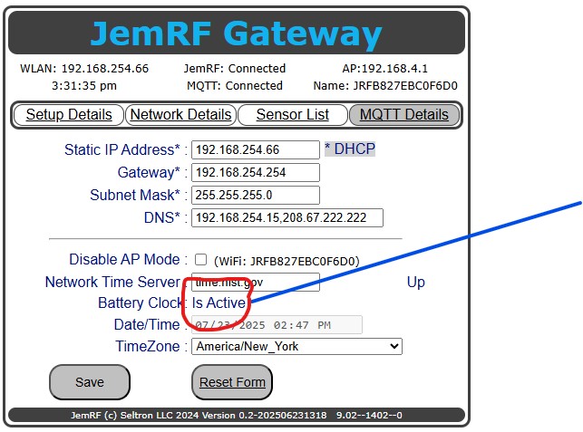
If the RTC modules is installed and working correctly, on the Network Details page, image R2, the Battery Clock will show Active.
 R2
R2
If the RTC is installed and not working is indicated by:
- On the Network Tab, the Battery Clock shows Inactive
Install/Replace the Dry Contact Relay Module
Currently, this replacement requires the Smart Gateway to be returned to the manufacturer for processing. If the dry contact option is installed and not working:
- Looking inside the relay module there should be lights on as shown above in image C1, arrow 1. Red is power and Green is indicates the relay is On indicating the Gateway is working correctly.
Replacement of Front Panel Lights
Currently, this replacement requires the Smart Gateway to be returned to the manufacturer for processing.
- Future updates will provide details on replacing the Front Panel.