Product Description
The wireless motion sensor is a kit that requires some basic construction of the following components as described in this tutorial:
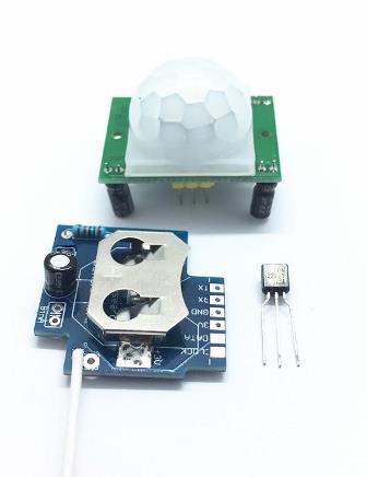
- Bottom left in above picture - RF Module Wireless switch (the kit includes a CR2032 battery to power the RF module)
- Top of above picture - Motion sensor (the kit does not include a 5V power source for the motion sensor)
- Bottom right in above picture - Transistor (NPN2222 included in the kit)
The RF module of the motion sensor acts the same as a wireless switch wireless switch except for it being triggered by the external motion sensor instead of a tactile switch.
Installation
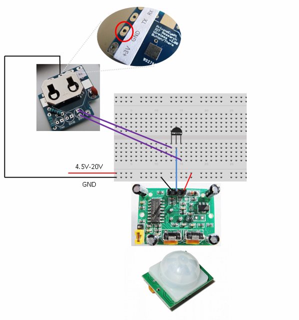
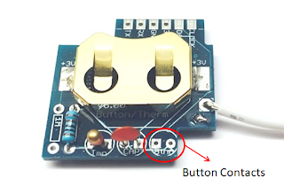
Connect the motion sensor to the transmitter as shown in the below diagram. The wireless transmitter (top left) will send a signal when the two contacts (see image below with Button Contacts label) are closed (i.e. bridged). The three legged transistor in the middle of the breadboard (Not Included) in the diagram acts as a switch. It will close the circuit between the outer two legs of the npn2222a transistor when a signal (3V current) is sent to the middle leg. The motion sensor sends 3V current to the middle leg when motion is detected. Both devices (transmitter and motion sensor) have two separate supply voltages (3.3V for the wireless switch, which uses a 3.3V coin cell battery and 4.5V-20V for the motion sensor, e.g. 4xAA or a 9V battery). Don’t use 3x1.5V batteries for the motion sensor as it is too close to it’s 4.5V minimum boundary, rather use 4x1.5V.
Sensor testing
- See the testing section of this documentation
Product Specifications
Electrical
- 2.2-3.3V Powered by CR2032 coin cell battery for the RF module (wireless switch)
- 5-20V power supply for the motion sensor
- Alternatively the RF module can be powered off the same 5-20V power supply of the motion sensor with the addition of a 5V-20V to 2.2-3.3V converter
- The RF module can be externally powered by soldering to the 3V3 and GND through holes on the PCB
- Battery consumption of the RF module is dependent on the frequency of motion detections
Functional
- Standard JemRF wireless sensor, refer RF Communications section for all the details
- Highly configurable
Messaging details
- BUTTONON- (sent when transitioning from water to no water between the forks)
- BUTTONOFF (sent when water is detected)
- STATEON- (the sensor state is sent every INTVL minutes if no motion detected)
- STATEOFF (the sensor state is sent every INTVL minutes if motion is detected)
- BUTTON (the BUTTON command requests the the state from the sensor)
Physical
- 36mm x 36mm x 15mm case size (1.42” x 1.42” x .59”) for the RF module
- No casing is provided for the external motion sensor and associated wiring
Default configuration
- Type 1 (Type 1 sensor)
- NOMSG3 (Sends 3 sensor readings every time the sensor state changes)
- INTVL030 (Sends the sensor state every 30 minutes)
- SLEEP (puts the device into sleep mode)
- Refer device configuration for more details