This page explains the JEMRF Wireless Water Sensor
Product Description
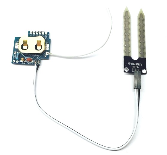
The Wireless Water Sensor can sense the presence of water between the forks of the external water sensor. Usually used for flood alarms for housing, but can also be used as a rain detector.
Installation
- There are three external parts in addition to the RF module, shown in the below diagram. The device on the right hand side of below picture is a variable analog to digital convertor that can be discarded or used for one of your other projects.
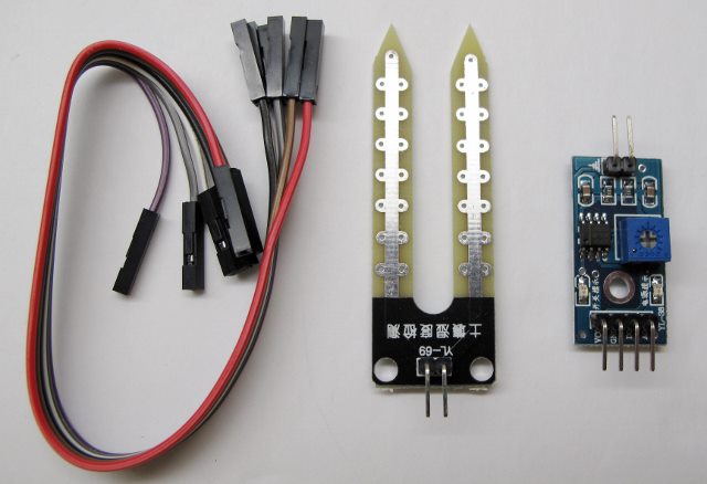
Tip: The variable analog to digital converter measures the analog reading across the two analog inputs and triggers the digital pin HIGH when the analog reading exceeds the variable setting (set by the screw adjuster).This part is not needed for this project but can be used for moisture level detection (e.g. the moisture level of soil). There is also an analog output on the device that gives you an analog reading of the moisture level.
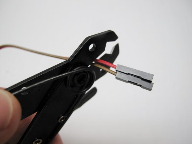
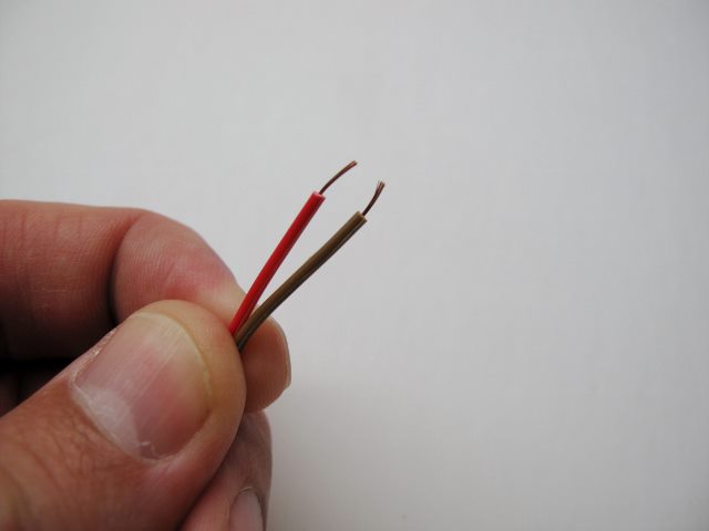
- Cut off the female connectors from one side of the two jumper wires provided and strip away some of the shielding.
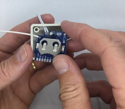
- Solder the two wires to the RF Module contacts labeled BTN and connect the two female jumper connectors to the forked water sensor.
-
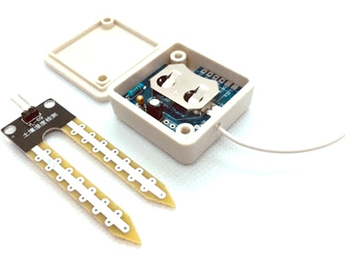
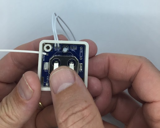
The RF module is installed in the sensor enclosure by removing the two female jumper connectors and threading them through the sensor case hole and re-attaching them to the forked water sensor.
-
Install battery and close enclosure as described here.
-
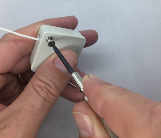
Thread the antennae through the the case enclosure and push the sensor into place within the enclose
- Close the enclosure case using a Phillips screw driver
Sensor testing
- See the testing section of this documentation
Product Specifications
Electrical
- 2.2-3.3V
- Powered by CR2032 coin cell battery
- Can be externally powered by soldering to the 3V3 and GND through holes on the PCB
- If used for flood sensing then this device will normally trigger infrequently and the battery will last over a year
Functional
- Standard JemRF wireless sensor, refer RF Communications section for all the details
- Highly configurable
Messaging details
- BUTTONON- (sent when transitioning from water to no water between the forks)
- BUTTONOFF (sent when water is detected)
- STATEON- (the sensor state is sent every INYVL minutes if no water detected)
- STATEOFF (the sensor state is sent every INTVL minutes if water is detected)
- BUTTON (the BUTTON command requests the the state from the sensor)
Physical
- 36mm x 36mm x 15mm case size (1.42” x 1.42” x .59”)
Default configuration
- Type 1 (Type 1 sensor)
- NOMSG3 (Sends 3 sensor readings every time the sensor state changes)
- INTVL030 (Sends the sensor state every 30 minutes)
- SLEEP (puts the device into sleep mode)
- Refer device configuration for more details
Note: Did you know this sensor is also a multi function sensor?