Introduction to the JemRF Smart Gateway
The JemRF Smart Gateway stands as a cutting-edge solution for safeguarding and managing sensor data. Designed with advanced data security features, it captures and timestamps every sensor measurement, ensuring comprehensive logging of all data points. This robust device securely stores measurements until they are successfully transmitted to the monitoring server, guaranteeing data integrity and reliability.
Engineered for versatility, the Smart Gateway can function autonomously without an internet connection, seamlessly communicating with a private network server. It offers full-spectrum management and monitoring capabilities, granting users complete control over its extensive features. Additionally, it provides real-time insights into the internal health of both the operating firmware and hardware, ensuring optimal performance and reliability.
This innovative gateway embodies the pinnacle of data management technology, delivering unparalleled control and security for all your sensor data needs.
Features
The Smart Gateway has two primary protocols to send data measurements to the monitoring service. It uses secure HTTPS connections to the JemRF Monitoring Service as the main protocol. It also provides connections to an MQTT Broker for more versal data exchange with other data processing tools. The Smart Gateway now supports the SparkPlug B MQTT message protocol, expanding its MQTT capabilities. It can detect and report operational issues to an MQTT Broker and provide an external open/close contact to reflect the Gateway’s health.
Internal data logging and storing eliminate potential data loss in case of network connection failure. When the network connection is restored, any data captured while the network was down is backfilled to the cloud service or Server.
The hardware features provide Power over Ethernet (POE) or from a USB-C power source.
The unit has three status lights for:
- The State of the Server
- The status of the connection to the Server
- The status of the MQTT Broker.
Additional features include an internal battery-powered clock that ensures all the Gateways know the current time upon power up or when they cannot reach a network time server. You also have the option to manually input the local time if necessary.
The Smart Gateway can run standalone without connecting to a remote server or with an MQTT Broker. At the bottom of the Sensor List, there is an option to download today’s readings or schedule sending end-of-day readings to a Secure File Transfer (SFTP) or Windows file share.
The Smart Gateway provides an internal local WiFi hotpot on first use and setting up the Gateway.
Each form guides the user when making changes, by turning yellow the field that has new information as well as the Save button for those changes will turn Yellow. This provides feedback and a change is requested but has not been completed.
Controlling the Smart Gateway
During the initial setup, the Smart Gateway creates a local WiFi hotpot. The system control and health User Interface (UI) form uses an internal Web server, which is accessed using its IP address.
Once connected to the Gateway, there are four primary detail settings tabs.
- The Setup Details tab is for basic settings.
- The Network Details tab is for network features and services.
- The Sensor List tab displays the most recent message from each sensor.
- The MQTT Settings tab is for entering the address of the MQTT Broker and necessary credentials.
Each tab guides the user when making modifications. The forms indicate changes by turning the edited field and the Save button yellow, signaling that the changes have not been saved.
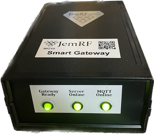
Status Lights
On the front panel are three display lights to indicate operational status of the gateway.
The Gateway Ready light, when Green indicates all applications are operational and it is online and ready to process data. If the Gateway Ready is off indicates there is an internal error. Internal errors will cause the External Connection status will change from Online to Off/Failure. The light will go RED to indicate a serious problem.
The Gateway Ready will go RED for these operation issues:
- There has been no new data received in over 6 minutes.
- MQTT Enabled but the MQTT Broker connection has failed for more than 2 minutes.
- If the reporting Server is assigned but not working
- Internal temperature is above 160°F
The Server Online light when Green indicates the connection to the monitoring server is connected and operational. If RED, that indicates a loss of connection to the monitoring server. If off, that indicates the monitoring server is not set.
The MQTT Online light when Green indicates the connection to the MQTT Broker is operational and working. If off, then the MQTT process has not been Enabled. A RED light indicates the connection to the MQTT Broker has been lost.
External Connections
The image below shows the Smart Gateway Interface Panel. It offers an option for USB-C Power and an Ethernet Interface, which can provide power when connected to a POE switch.
An optional feature is a dry contact interface to alert external facility control systems when the Gateway is On, Off, or in a Failed State.
- The Blue Online is connected to the Common if the Gateway is working correctly.
- The Orange Off/Failure is connected to Common if the Gateway is powered Off or there is an internal Alarm.
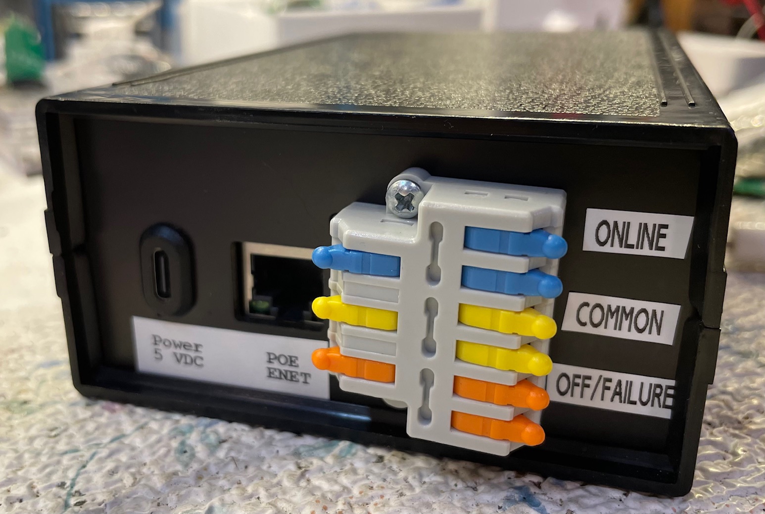
The levers lift and lock open to allow wire to be inserted into the connector then closed to lock down on the wire. Wire sizes supported range from as small as 28 gauge up to 12 gauge. Connection is designed for low voltage and low current AC or DC monitoring systems.
The external contacts are connected between Common and Online if all is working correctly. On a failure condition, the contacts open between Common and Online and close between Common and Off/Failure.
Failure conditions are:
- Internal application failure detected.
- Internal temperature is above 160°F
- The network connection is lost