What you will need
- ESP32 Development board. There are many variants available but any one will do. If you plan also connect JemRF wireless sensors then make sure GPIO pins 16 (TX2) and 17 (RX2) (Serial Port 2) are exposed.
- Micro USB to USB 2.0 connector to connect the ESP32 to a PC.
- A PC is required to load firmware on the ESP32. We will be using the Arduino IDE that has client available for Windows, Mac or Linux.
- Arduino ESP32 development environment setup (covered in the previous tutorial).
- Alarm system switches (reed switches, or any tactile switch circuit that open and closes a circuit - e.g. a motion sensor like this), and some wire.
- Prototyping breadboard (optional).
- If you want all alarm related parts in a kit then have a look at the DIY Alarm Kit
What you need to know
- Some basic low voltage electrical experience is advantageous but not necessary. The electrical construction is very basic and could be achieved with no knowledge of electronics.
- Some basic programming knowledge and prior experience with the Arduino IDE. Again not absolutely necessary but it will make the learning curve a bit easier.
Step 1 - Connect switches to the ESP32 Development Board
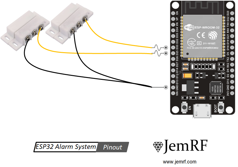
Following the wiring shown in the top picture connect the two connectors of the tactile switch. One wire goes to a free GPIO pin labeled DXX on the ESP32 Development Board (any one will do), and the other wire goes to GND. The ESP32 Development Board has two GND connectors you can use. If you have multiple switches then connect all the GND wires together (as shown with the two black wires in the picture) and connect to a single GND on the ESP32 Development Board.
Step 2 - Configure the sketch with your WIFI and PrivateEyePi details
In the previous tutorial we showed you how to setup up the development environment and you downloaded the JemRF RFLIB library. Now open up the privateeyepi sketch from the examples folder (File->Examples->rflib-master->privateeyepi).
rflib-master example folder then you may not have shut down the Arduino IDE and started it up again.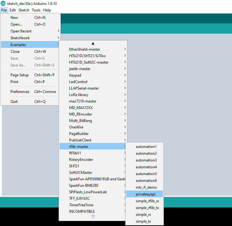
Now save a copy of the example sketch by selecting File->Save As from the main menu and giving it a new name. This will create a new folder in your Arduino directory with the name you gave to it, as well as an .ino file in the new directory.
Near the top of the sketch you will see the following code:
const char* pep_token = ""; //Enter your PrivateEyePi token between quotes
const char* ssid      = ""; //Enter your WIFI router SSID between quotes
const char* password  = ""; //Enter your WIFI password SSID between quotes
//Enter wired sensors here
//Add ,{xx,'s',0} settings for every wired sensor whee xx is the GPIO number
//GPIO 15 and 19 are configures as follows:
uint8_t wired_sensors[20][3] = {{15,'s',0},{19,'s',0}};
Make the following changes:
- Enter your PrivateEyePi token in between the quotes after
pep_token =.
- Enter your WIFI SSID name in between the quotes after
ssid =. The SSID is the name your WIFI router advertises. - Enter your WIFI password in between the quotes
password =. - Lastly change the following line to reflect the GPIO numbers you want to connect to reed switches.
uint8_t wired_sensors[20][3] = {{15,'s',0},{19,'s',0}};
For example in the picture at the top of this tutorial the two switches are connected to D25 and D33. Therefore you would change the configuration to be the following:
uint8_t wired_sensors[20][3] = {{25,'s',0},{33,'s',0}};
If you wanted to have three switches and add another switch to D32 then you would change the configuration to the following:
uint8_t wired_sensors[20][3] = {{25,'s',0},{33,'s',0},{32,'s',0}};
Step 3 - Load the privateeyepi sketch onto the ESP 32 Development Board
Click the right arrow button near the top left of the Arduino IDE.
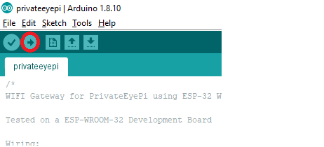
The sketch will compile and you will a green progress bar as it is loaded onto the ESP32 Development Board. Once the upload is complete you will see Done uploading. in the status bar.
Step 4 - Test the alarm system
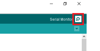
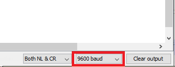
Click the serial monitor on the top right of the Arduino IDE and observe the messages on the screen.
Set the baud rate to 9600 using the drop down box on the bottom right of the monitor window:
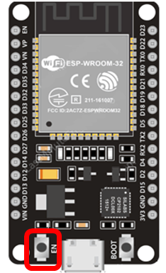
Push the EN button the ESP32 Development Board to reset the device.
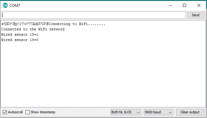
Monitor the progress as it logs into your WIFI router and configures the switches you configured in Step 2. You should see something like this:
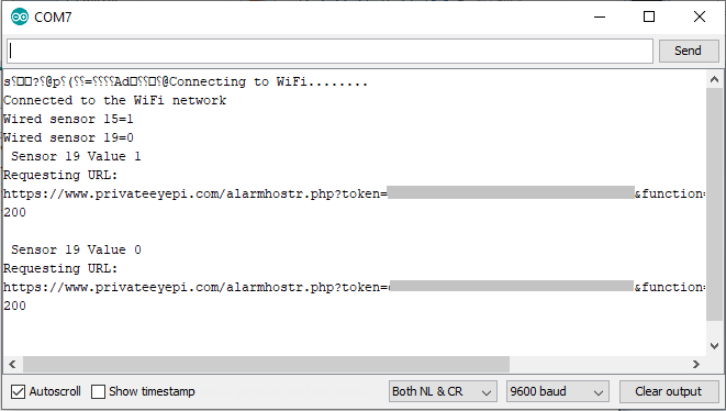
Open and close one of the your switches to confirm that the device is able to detect the open/close and data is being sent OK to PrivateEyePi. You should see something like this:
Lastly log in to PrivateEyePi and verify the switch status indicators are changing from green to red as the switches open.
Step 5 - Set up email alerts
PrivateEyePi has the ability to configure email alerts when an alarm is triggered. Emails can be triggered using the Standard Alarm Rules setting in the PrivateEyePi Config menu option or through rules you have configured with an email action. When an email alert is triggered a message is passed back to the ESP32 Development Board notifying it of an email alert and the ESP32 sends the email (not the server). If you want email alerts then you need to configure your email account details within the ESP32 code. Also remember to add the email addresses (using the Email menu option in PrivateEyePi) to which you want the notifications sent to.
There are four settings you need to know:
- Email user name (usually the email address)
- Email password
- SMTP Server
- SMTP Port
You usually obtain these details from your email provider, however there are a number of third party email delivery service providers that you can use to send emails for you.
The above four settings can be configured in your privateeyepi sketch. Look for the following lines near the top of the sketch:
//Email alert configuration
const char* smtp_corp="";
const char* smtp_password="";
const char* smtp_user="";
const uint8_t smtp_port=80;
Enter the SMTP Corporation address, user name and password between the quotes, and replace the 80 with the SMTP port of your provider.
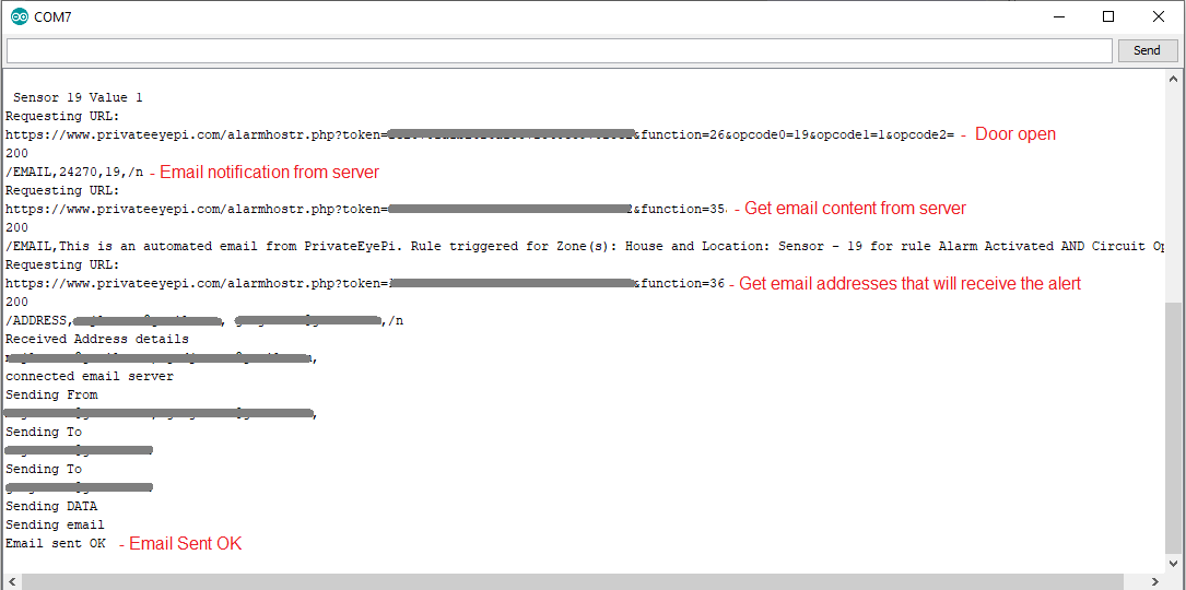
Upload the sketch as you did in Step 3 and trigger an alarm to test if you receive an email. Highlighted in red below are descriptions of the communications between the ESP32 and PrivateEyePi to obtain email addresses that will receive the alert in addition to the message body details (sensor number and alarm zone description).
Step 6 - Set up a chime and alarm
PrivateEyePi has two audible notification features : Alarm and Chime. Alarm is triggered with through the Standard alarm rules set in the Config menu option in PrivateEyePi or as a rule action. A Chime is a rule action (e.g. when door open sound the chime). Below are the instructions for building the Alarm and Chime circuit and making configuration changes on the ESP32 Development Board.
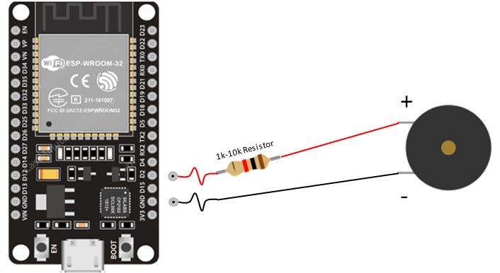
- Connect the positive (+) leg of the Piezzo buzzer to pin D5 on the ESP32 Development Board using a 1k-10k resistor
- Connect the negative (-) leg of the Piezzo buzzer to Ground (GND)
- You can find the configuration for Chime and Alarm in
~\Adruino\Libraries\rflib-master\pep.h
#define SIREN_PIN 2
#define SIREN_DURATION 120
#define SIREN_DELAY  30
#define CHIME_PIN 2
- The
SIREN_DURATIONis the amount of time the siren will sound when an alarm is triggered. - The
SIREN_DELAYis the amount of time that will elapse between an alarm being triggered and the alarm sounding. During this time the buzzer will beep slowly allowing you time to switch off the alarm before it sounds. SIREN_PINandCHIME_PINare the pin numbers for the chime and alarm (you can use one Piezzo buzzer for both, or separate buzzers)